Mastering IR detection (part 1)
Studying opamps, documenting phase-reversal, and setting up for the best IR detection this world has ever seen.
- experiment
What I’m trying to achieve
Today I want to build a simple circuit to detect IR using a photodiode.
Building the circuit
We start by characterizing the opamp I will be using.
The datasheet I found for the TL082 is a bit hard to understand, so I want to test the input ranges myself to see what analog outputs my photodiode is allowed to give.
I built this circuit:
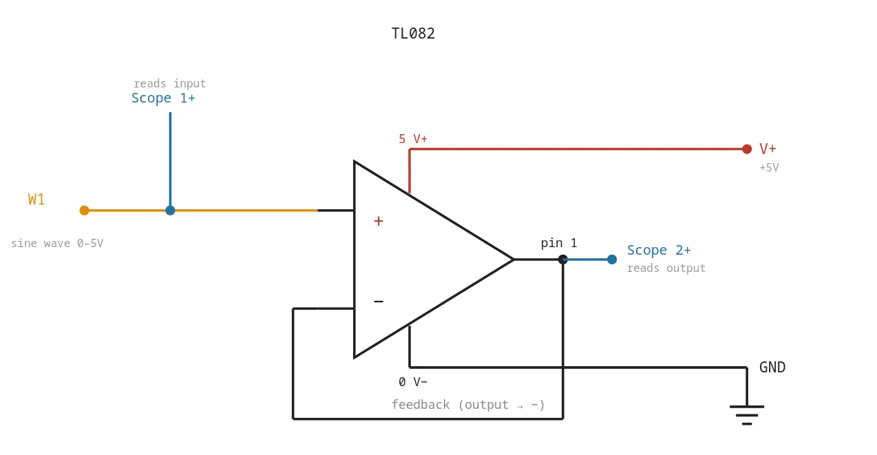
Running it with a sine wave input gave me this result:
I don’t quite understand what’s happening… particularly what is going on with that spike to 1.6V, then surprising saturation at the output pin once my input pin is sufficiently low enough. I must explore more.
The TL082IP
This is the opamp I have right now. According to the datasheet:
| PARAMETER | MIN | TYP | MAX | UNIT | ||
|---|---|---|---|---|---|---|
| V_CM | Common-mode voltage range | ±11 | -12 to 15 | V |
The common-mode (with assumed rails at -15 V and 15 V) is -12 V to 15 V… This means, roughly, we should expect “normal” behaviour around 3 V to 5 V on our input rail. We’re seeing something like a phase-reversal, which is apparently a common failure mode for these opamps.
In any case, now that we have a profile of this opamp operating at this supply range, we can carry on.
The circuit we’re aiming for
Today I will be building this circuit:
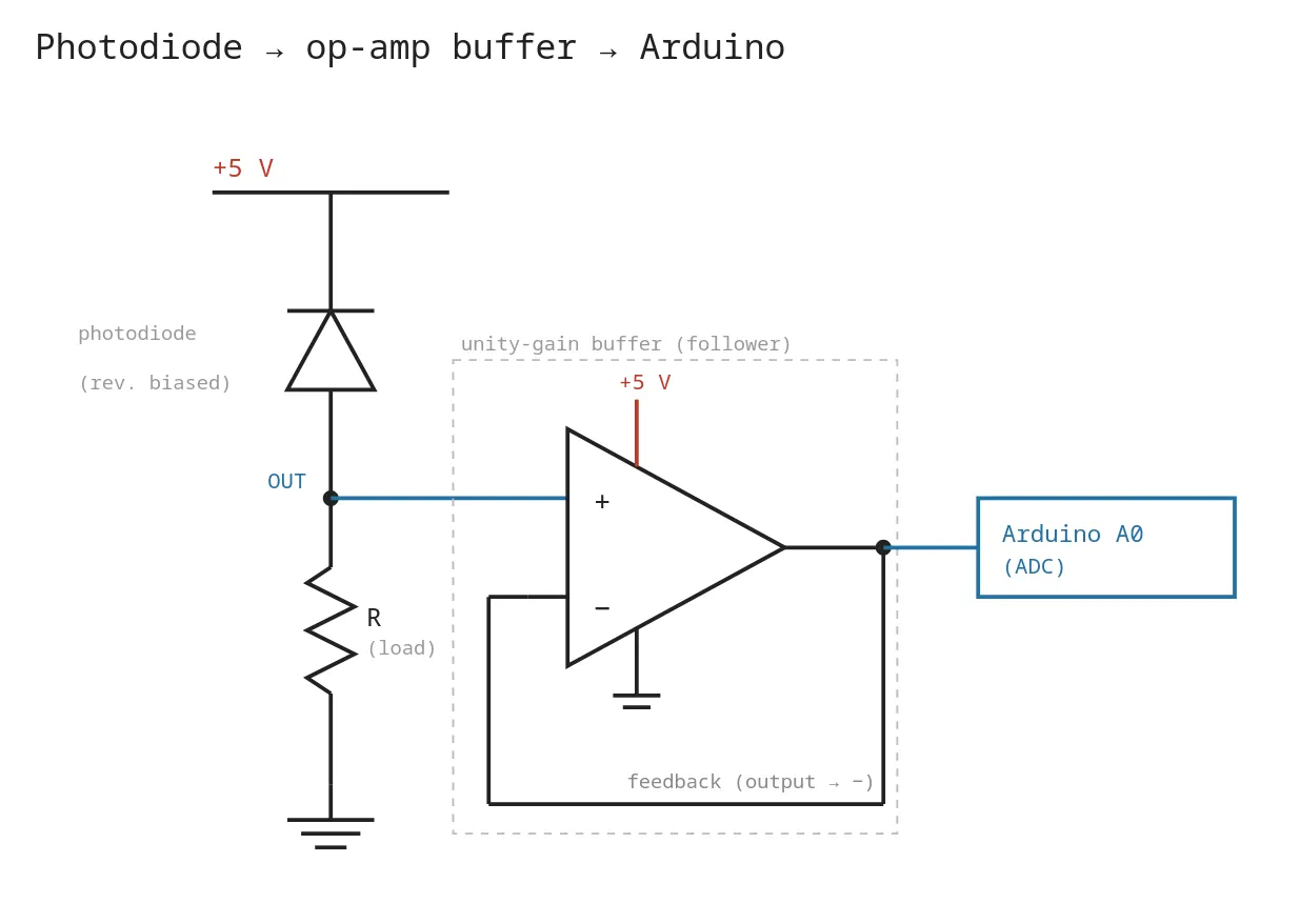
But… because of what we just learned about phase-reversal, we need to bias our OUT to operate within ~1.6 V to 4.5 V. So, I’ll be building this:
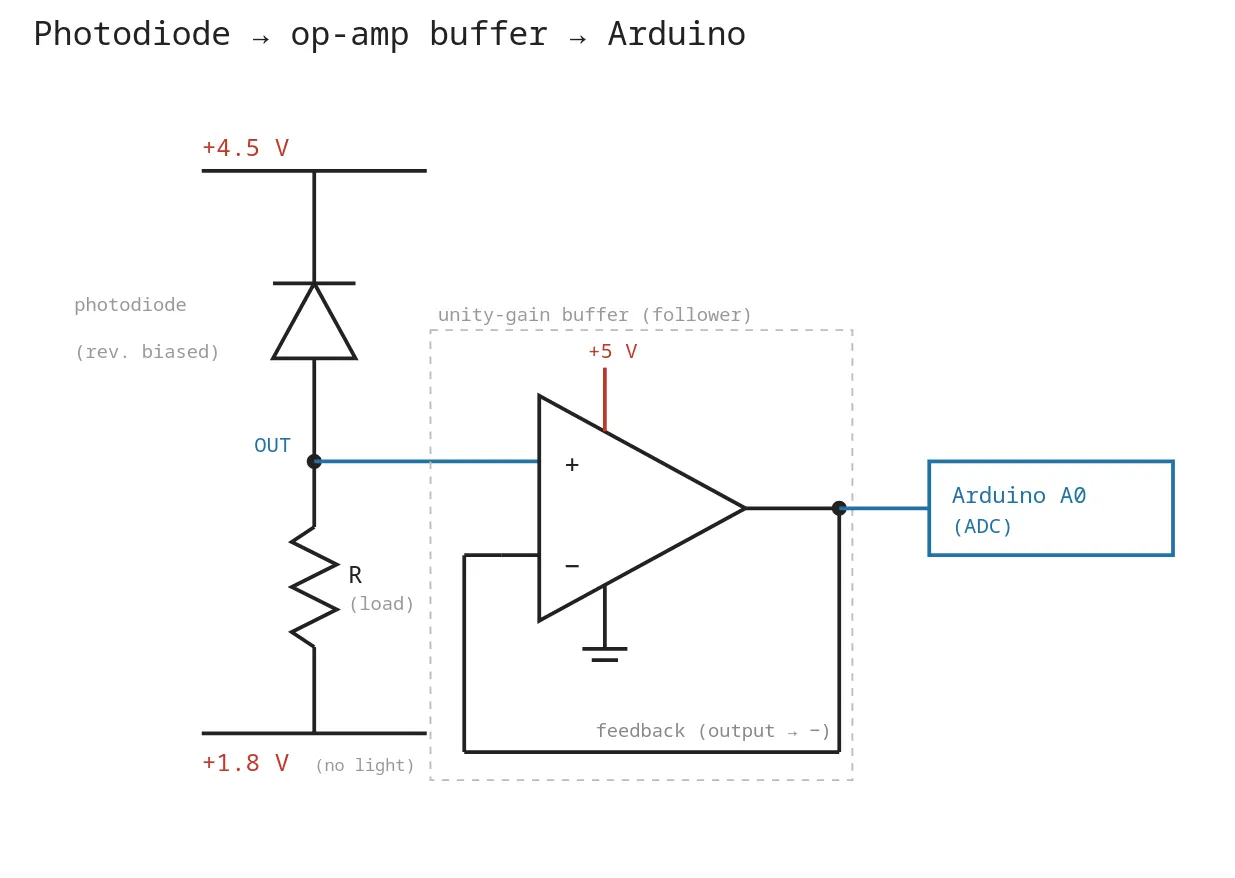
And in order to do this… I will need to use the second opamp in the TL082IP IC. I need to make a voltage divider and take the floppy output, run it through a unity-gain opamp and use this as the reference floor to my photodiode circuit.
(This will make more sense tomorrow when I have images for you.)
Driving questions
- Is there any interference from one opamp that will impact the other on the TL082IP opamp?
- How should I build this circuit to reduce wire-clutter?
Next
- Move to the project lab and build the stiff supply!
- Create the test outside test-plan to get good baselines on the sun.